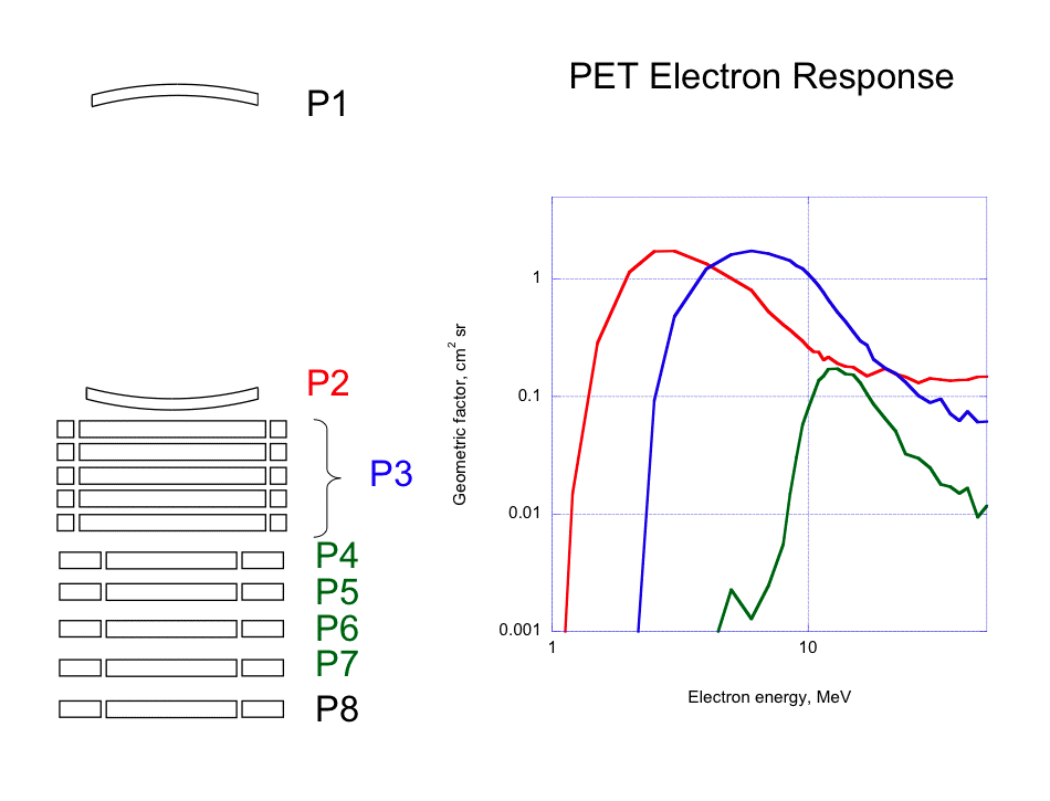

The figure above is a cross section, to scale, of the detector and guard active elements of the PET (Proton/Electron Telescope) sensor aboard SAMPEX, along with a plot showing EGS4 simulations of the response of three channels to electrons. The first two detectors are shaped like spherical "caps" to reduce path length variations for particles within the broad acceptance cone of two-detector (P1 and P2) events. P3 consists of a stack of five detector wafers with guard rings around each; P4 through P8 are individual detectors with guard rings. (Guard rings are usually used in anticoincidence, to reject particles that either enter or leave the stack through the side rather than through P1.) The three curves in the plot at right are color-coded to show the detectors involved in each channel: red is for electrons stopping in P2, blue is for electrons stopping anywhere in the P3 stack (after passing through and triggering P1 and P2, and not triggering any guard rings or deeper detectors, P4 and up), and green is for electrons stopping in P4 to P7 (after penetrating P1 through P3, and not triggering P8 or any guard rings). For a given particle stopping in the P3 stack, we do not have any way to tell in which of the five detector wafers the particle stopped; we are nominally able to distinguish particles stopping in P4, P5, P6, and P7, but often we sum these events together on the ground to improve statistics, which is why there is only one green curve in the plot for all four detectors.
For ions, straggling and scattering are much less important than for electrons, so energy channels and geometric factors can be more sharply defined simply by using range-energy relations. The table below gives the dimensions of the active areas of the P1 through P8 detectors and their separations (distances of midplanes from the midplane of P1), along with the acceptance cone half-angles and geometric factors defined by a coincidence of P1 with each detector (and all the detectors in between) and the energy bin defined by each range. This is in MeV for protons; channels would be numerically the same but in MeV/nuc for alpha particles. As noted above, we are not able to tell directly from the telemetry in which wafer of the P3 stack a particle stops; however, the energy deposited in P1, P2, and the P3 stack is pulse-height analyzed and included in the telemetry, so we are able to determine the energies of such particles, and can use that information to assign each one to the appropriate channel with the appropriate geometric factor.
 Back
to top of Data Pages
Back
to top of Data Pagesnew 17 September 2007